The assembly described here is NO MORE AVAILABLE. Here some data:
| Frequency range: according to customer order in the range from 100 to 1500 MHz, | |
| Tuning range: approx. +/- 5% around center frequency | |
| Output: 50 Ohm, +7 dBm (5 mW) | |
| Programming via RS232 interface (9600 Baud) | |
| Fix frequencies ( memory) : 16 frequencies can be stored in EEPROM, selectable by 4 switchen | |
| Modulation: dual modulation for perfect response from as low as 5 Hz up to 50 kHz FM (up to 76 kBaud FSK) | |
| Fine tuning +/- 20 kHz or more by DC voltage (potentiometer). Effective in RX and TX mode. | |
| RIT-Input (e.g. for doppler compensation), selectable for positive or negative df/du. Effective only in RX mode. | |
| AFC-Input (same as RIT but separate), selectable for positive or negative df/du. Effective only in RX mode. | |
| RIT, FINE and AFC can be disabled / enabled by software mommand. | |
| Power supply: 12 Volt +/- 20% or 5 Volt +/- 2%, 50-100 mA | |
| Temperature stability: The output frequency is temperature-compensated from -10 to +70 C by temperature sensor and software digital control of reference quartz. | |
| Dimensions: approx. 55 x 90 mm | |
| PTT: in 'TX'-mode, the oscillator frequency may be shiftes bi some kHz for not to interfere the receiver frequency. | |
| Frequency input: The operating frequency is directly input in Hz via RS232, ranging from 0 to 99 GHz. The built-in processor calculates the oscillator frequency considering programmed IF or converter shift and (if applicable) frequency multipliers. | |
| Step width of oscillator: approx. 10 to 50 Hz. Programmable in 1 Hz steps. | |
| BUS-capability: For complex systems, you may control many PLL or other FUNKBUS devices parallel. Each device on the bus has a programmable unique address. |
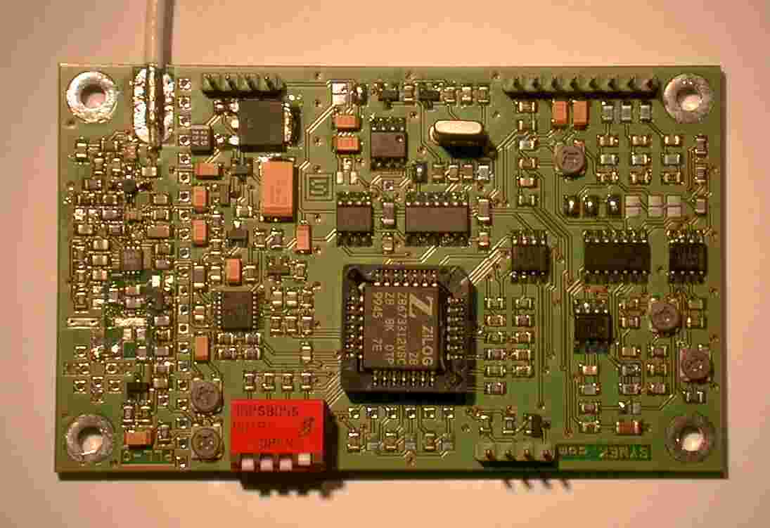
PLL-B Prototype oscillator
Applications:
| FM Master oscillator for FM transmitters, data radios, FM radios, FM-repeaters etc. | |
| Oscillator for high quality receivers (satellite receiver stations, FM receivers etc.) | |
| Test signal generator for amateur radio and commercial applications | |
| Oscillator for satellite ground stations using converters |
What do we plan?
We are planning to develop a series of assemblies to built special transmitters and receivers.
The PLL and the BUS RS232-FUNKBUS-adapter are the first parts available.
In future, we shall add the following assemblies:
| PLL Programmable precision oscillator (AVAILABLE SOON) | |
| FE7 RF front end for 435 MHz UHF, 71 MHz IF output to URX, 506 MHz LO input (from PLL) | |
| FE2 RF front end for 1250 MHz (23 cm L-Band) with frequency
doubler for LO, 110 MHz IF output to URX, 570 MHz LO input (from PLL) | |
| FE1 RF front end for 2450 MHz (13 cm S-Band) with
frequency multiplyer (4x) for LO, 110 MHz IF output to URX, 585 MHz LO input (from PLL) | |
| URX Programmable receiver with switchable filters (up to 300 kHz bandwidth) for 45 to 150 MHz | |
| IFD Receiver for 10.7 or 71.00 MHz IF, wide band FM for up to 76 kBaud data receivers. (AVAILABLE) | |
| PA7 RF power amplifier for transmitters, input: 5 mW, output: 25 W | |
| ARO Antenna controller for tracking satellites using a FUNKBUS system | |
| MUX Multiplexer for RF / Antenna / AF or DC switching unsing a FUNKBUS system | |
| BUS Converter to connect a computer RS232 to the FUNKBUS system (required 1x per system) (AVAILABLE) |
User Commands (some extracts from the users manual)
The commands used with the PLL have the syntax:
*AACCxxxxx <CR>
| First character is an asterisk (h2A) | |
| second and third
character is the device address, which must match the address stored in PLL-EEPROM | |
| CC defines the command to be executed | |
| xxxx is the (optional) parameter field for the specific command |
With the following examples, we assume the address of the PLL device to be 'P1'.
Setting the Frequency (immediately)
*P1VO=00435000000 <CR>
The operating frequency is immediately set to 435 MHz.
(Note: VO = 'VFO'-mode, the 'O' is the character 'Oscar', not figure zero)
Programming the 16 frequencies
*P1Z0=00435000000 <CR>
The channel Number 0 is programmed to 435 MHz.
(Note: Z0 = Channel Zero, the '0' is the figure zero, not the character 'Oscar')
*P1Z1=00435000000 <CR>
The channel Number 1 is programmed to 435 MHz.
*P1Zy=00435000000 <CR>
The channel Number y (0, 1, 2...9, A, B, C, D, E, F is programmed to 435 MHz.